Model Definition
The first step in creating a Chromatik project is to define your lighting model, which includes:
- Placement and number of lighting fixtures (typically addressable LEDs)
- Orientation of fixtures in 3D space
- Protocols and addressing to communicate with lights
- Output settings and corrections
- Settings to render a simluation of your model
These tasks are accomplished in the left-pane MODEL tab.
Coordinate System
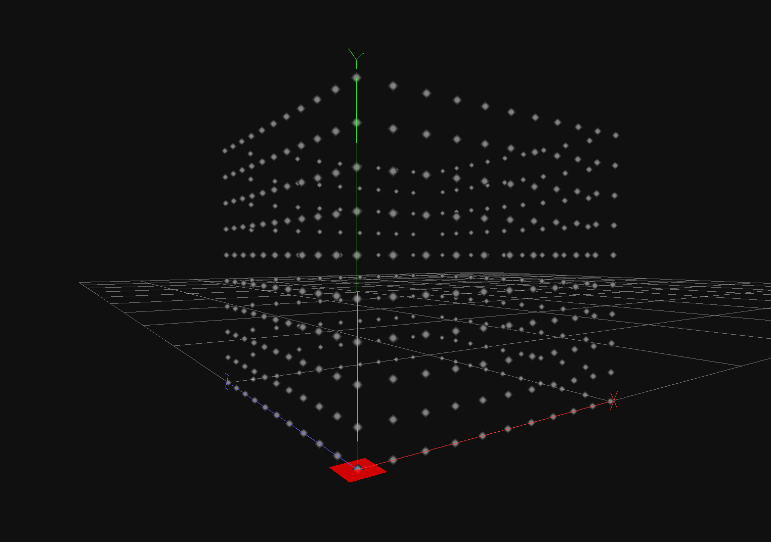
Chromatik uses a left-handed coordinate system.
+Xpoints to the viewer's right+Ypoints up to the sky+Zpoints into the scene, away from the viewer
Fixture orientation is generally specified via Yaw, Pitch and Roll.
- Yaw rotates about the
+Yaxis — positive is clockwise from above, head turning right - Pitch rotates about the
+Xaxis — positive tilts forward, chin to chest - Roll rotates about the
+Zaxis — positive rolls left ear to left shoulder
NOTE: Dimensional units in Chromatik fixture specifications are arbitrary. It is up to you to decide the most intuitive way to apply dimensions to your project. Most animation routines operate in normalized space, based upon the overall scale of the model. Unit specification and conversation may be considered in a future version.
Managing Fixtures
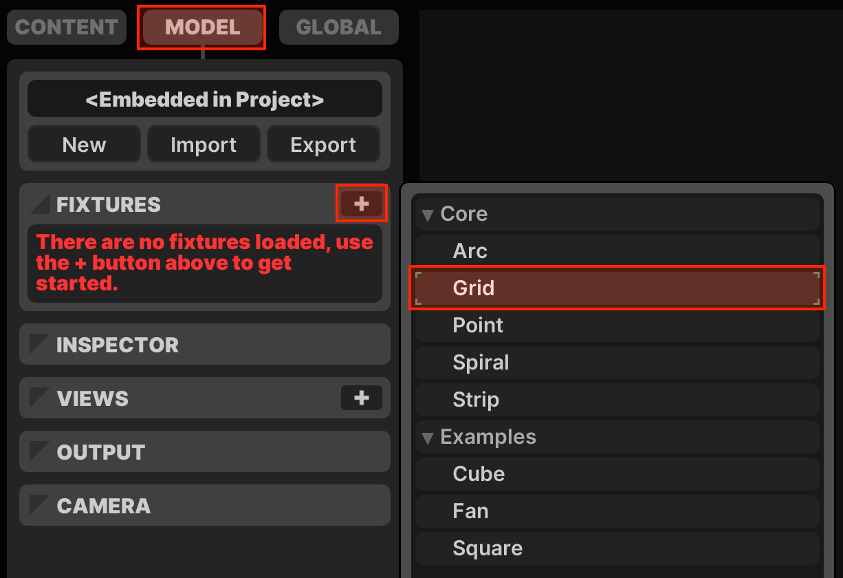
Fixtures are added in the FIXTURES section. Use the button to open the Fixture Chooser. Basic geometric forms are included by default: Arc, Grid, Point, Spiral and Strip.
Fixtures that have been added appear in the Fixture List, with a set of per-fixture controls.
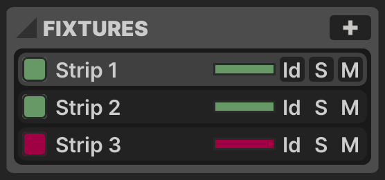
- Enabled: Toggle box, whether output to this fixture is active
- Label: Fixture name, renamable with ⌘R
- Brightnesss: Slider to adjust fixture output brightness
- Id: Override normal animation, this fixture pulses red
- Solo: Animate this fixture only, all others blackout
- Mute: Blackout this fixture (data is still sent)
NOTE: when the Enabled switch for a fixture is turned off, the fixture is still part of the animation model and continues to appear in the Preview Window, but network output is completely stopped. In this situation, lighting hardware may continue displaying the last data that was sent. It therefore may be prefereable to fade out or Mute the fixture, both of which continue sending data to the fixture instructing it to display all black.
Fixtures in the list may be renamed with ⌘R, reordered with drag-and-drop or ⌘↑ + ⌘↓, duplicated with ⌘D and deleted with DELETE.
Multi-Selection
Modifier keys can be held while clicking to select multiple fixtures ⌘ or a range of fixtures ⇧. The Enabled, Brightness, Id and DELETE operations all respect multi-selection.
Deactivation
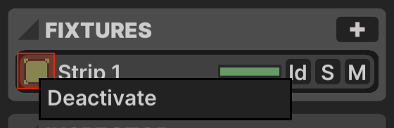
It is possible to Deactivate a fixture entirely by right-clicking the Enabled button to open a context menu. In this case, not only is network output stopped, but the fixture is removed entirely from the model and is completely unavailable to the animation engine. The Enabled toggle turns red in this situation, as is seen with Strip 3 above.
Fixture Settings
Settings for the currently focused Fixture are displayed in the INSPECTOR section below.
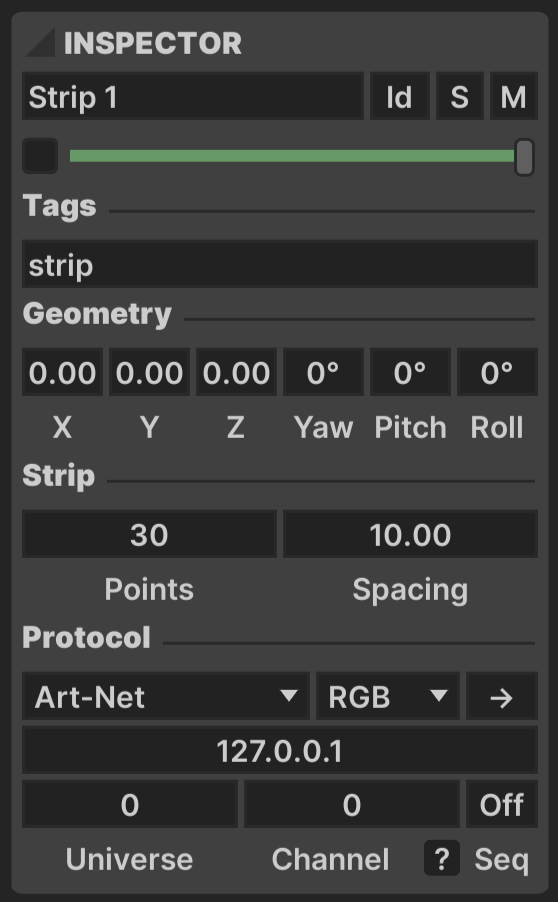
The top section duplicates the controls found in the Fixture List.
- Label: Fixture name, renamable with ⌘R
- Enabled: Toggle box, whether output to this fixture is active
- Brightnesss: Slider to adjust fixture output brightness
- Id: Override normal animation, this fixture pulses red
- Solo: Animate this fixture only, all others blackout
- Mute: Blackout this fixture (data is still sent)
Tags
A list of arbitrary string tags may be applied to the fixture. Default tags are provided for the in-built types, though these may be removed. Tags are comma-separated or simply separated by spaces. Tags may only contain alphanumeric characters or the special characters _.-/.
Tags can be used by device implementations to query specific components in a model or to construct a View of the model.
Geometry
A base position is provided for all fixture types.
- X / Y / Z: reference point for the fixture position
- Yaw rotates about the
+Yaxis — positive is "clockwise" from above - Pitch rotates about the
+Xaxis — positive is a "forwards" tilt - Roll rotates about the
+Zaxis — positive is like rolling your head onto your left shoulder
Transform operations are performed in the fixed order indicated above. These values can be specified manually in the inspector, or by using Move Fixtures Mode ⇧⌘F as the Preview Window's Mouse Interaction Mode.
Fixture-Specific Parameters
- Arc: Points curving around a circular arc
- Points: Number of total points in the arc
- Radius: Radius of the arc
- Degrees: Number of degrees the arc covers
- Mode:
Origin/Centerspecifies how the arc is placed relative to fixture position
- Grid: Points laid out in a 2D grid
- Rows: Number of rows in the grid
- Row Spacing: Spacing between rows
- Columns: Number of columns in the grid
- Column Spacing: spacing between columns
- Wiring: How the points in the grid are physically wired, which may be a linear pattern by row, column, or zig-zagging across the two
- Point: A single point, no custom parameters, may be used with
Wbyte order mode to simulate any single-channel DMX output - Spiral: A strip wrapped in a helix pattern
- Points: Number of total points in the spiral
- Turns: Number of revolutions about the axis
- Radius: Radius from the outer spiral to its central axis
- Length: Lateral distance covered by the spiral's axis
- Strip: A linear strip of points
- Points: Number of total points in the strip
- Spacing: Spacing between points
Protocol
This section specifies the output protocol used to send color data for the fixture. A Byte Order dropdown specifies the order in which color bytes are sent, as well as whether a W (white) byte is included. A Reverse button is offered for Arc, Strip and Spiral fixture types to send pixels in reverse order.
All protocols have a Host setting to specify the reciever address (or broadcast address 255.255.255.255). Specific options for the protocols are as follows.
- Art-Net: Art-Net Ethernet Protocol
- Universe: Starting DMX universe number,
0-indexed - Channel: Starting DMX channel offset (
0-511) - Seq: Whether to send incrementing Art-Net sequence numbers (
0if unused)
- Universe: Starting DMX universe number,
- E1.31 sACN: Streaming ACN
- Universe: Starting DMX universe number,
0-indexed - Channel: Starting DMX channel offset (
0-511) - Priority: E1.31 Data Priority (
0-200)
- Universe: Starting DMX universe number,
- OPC: Open Pixel Control
- Transport: Transport layer may be either
UDPorTCP - Port: Receiver UDP/TCP port number
- Channel: OPC channel number (
0-255) - Offset: OPC output offset
- Transport: Transport layer may be either
- DDP: Distributed Display Protocol
- Offset: Data offset
- KiNET: Color Kinetics KiNET
- KiNET Port: Hardware output port (
0-255) - Channel: Starting DMX channel offset (
0-511)
- KiNET Port: Hardware output port (
DMX Channel Addressing
DMX Channels in Chromatik are a 0-indexed offset, with valid range 0-511. Many controllers and systems use 1-512 when referring to DMX Channels. Therefore, the number entered in Chromatik may need to be 1 less than the controller configuration value if that equipment works with the range 1-512.
DMX Universe Handling
For the DMX-based Art-Net and E1.31 sACN protocols, universe overflow is handled by automatically wrapping to the next universe when there insufficient space remains to fit all of a the bytes for a single pixel into the universe. For 3-byte RGB pixels, this means a DMX Universe would terminate at a length of 510 bytes, holding a total of 170 pixels. The next pixel would be placed on the next DMX Universe at DMX Channel 0.
If multiple fixtures overlap on the same DMX Universe they are automatically merged, so long as there are no collisions on any individual DMX Channel. If a collision is specified, an error message is shown and only the first fixture's output is sent.
Custom Fixtures
For large or complex projects, the simple geometries of the inbuilt types may not be sufficient, or it may be too cumbersome to specify massive numbers of individual fixtures. For this situation, a JSON-based .lxf file format offers the ability to write custom fixture types with arbitrary nesting and hierarchy, plus the ability to expose parameters in the UI.
These fixture definitions are placed in the ~/Chromatik/Fixtures folder and appear in the Fixture Chooser alongside the in-built types.
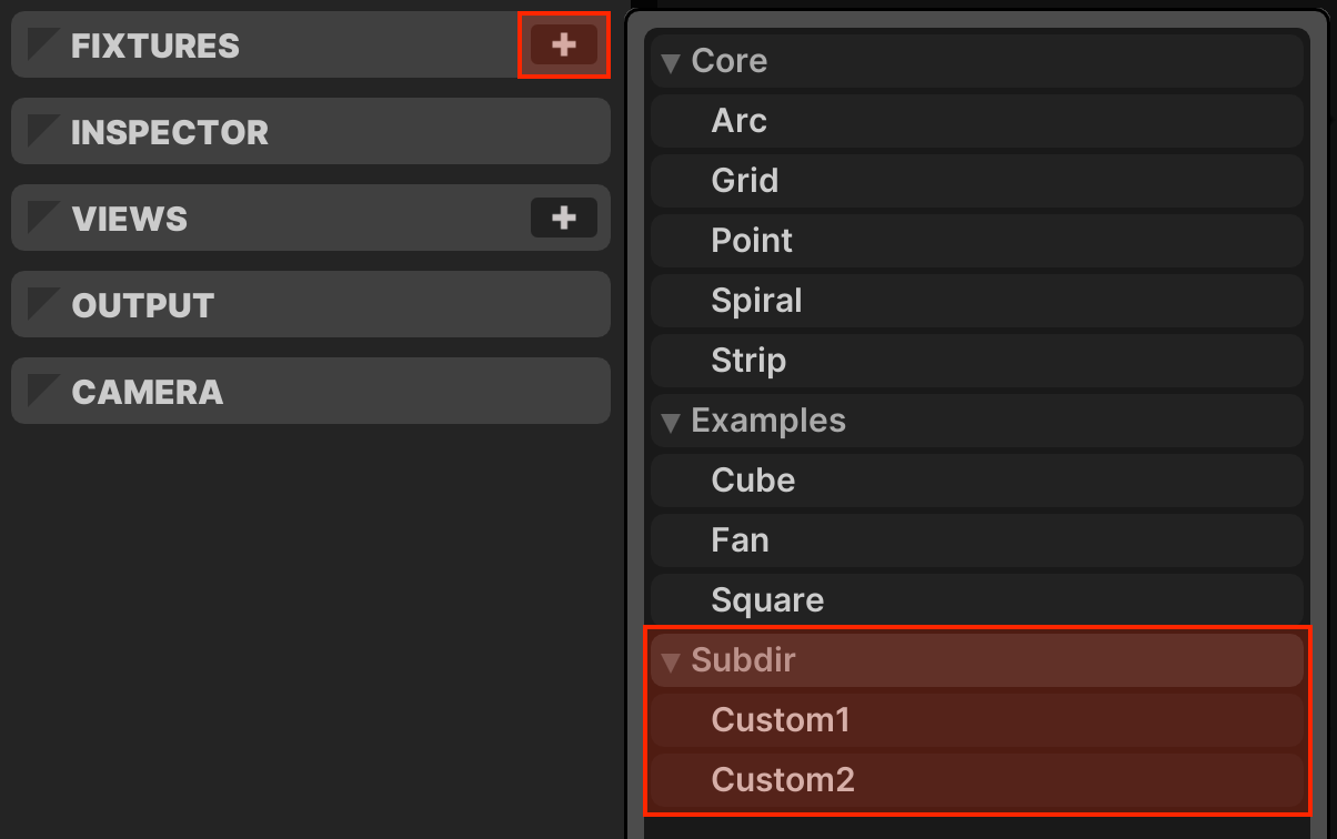
The format of these fixture files is covered in detail in Custom Fixtures →
Views
By default, all animation devices operate on the entire lighting model. However, it is often useful to have dedicated mixer channels or devices that operate upon only a portion of the model. For instance, you may have a lighting sculpture with two main elements that animate distinctly. This can be accomplished with Views.
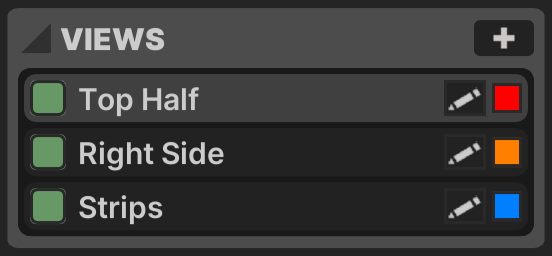
Views are managed in the VIEWS section of the left-pane MODEL tab. Use the button to create a new view.
Views in the list may be renamed with ⌘R, reordered with ⌘↑ + ⌘↓, duplicated with ⌘D and deleted with DELETE. An enabled button to the left of the view label toggles whether this view is available. A reference color selector box ![]() is also available on each view, making this view more easily identifiable when it is used elsewhere in the application.
is also available on each view, making this view more easily identifiable when it is used elsewhere in the application.
View Specification
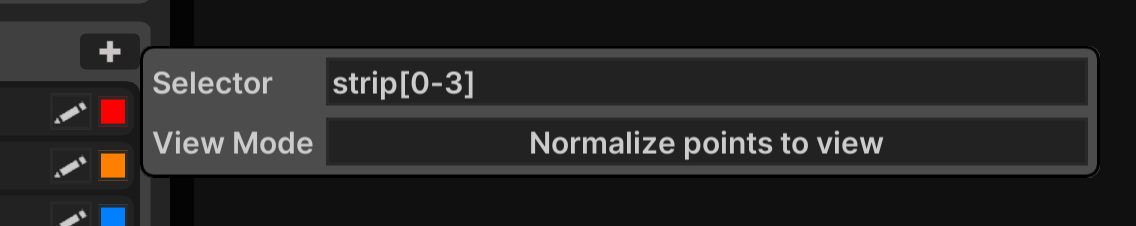
Selector
The View Selector is a text value which specifies which fixtures belong to the view using a minimal CSS-esque language. Fixtures are specified by referring to their tags.
strip: tag selector, all fixtures matching the tagstripstrip*: subgroup operator, each match on the selector is normalized independentlyline ; circle: group oprator, both selectors are in the view but they are normalized independentlyline , circle: union operator, fixtures matching either the taglineorcirclecube edge: descendant, fixtures matching the tagedgewhich descend from a fixture matchingcubecube > square: direct child, fixtures matching the tagsquarewhose immediate parent matchescubesquare & polygon: intersection operator, fixtures matching both of the tagssquareandpolygon
Range Modifiers
tag[n]:n-th fixture matching the tag,0-indexed, e.g.tag[0]is the first instancetag[n-m]: matches wherem > n, e.g.tag[0-3]is the first four instancestag[n:i]: matches starting fromnand incrementing byi, e.g.tag[1:3]selects1,4,7,...tag[n-m:i]: matches wherem > n, starting atnand incrementing byi, e.g.tag[1-4:3]selects1,4tag[:i]: matches from0incrementing byi, equivalent to[0:i]tag[even]: even indices, equivalent to[0:2], e.g.tag[0],tag[2],tag[4],...tag[odd]: odd indices, equivalent to[1:2], e.g.tag[1],tag[3],tag[5],...
Operators may be used in conjunction, e.g. parent[0] > strip[2-4] ; parent[1] strip[0-5] would create a view with two normalization groups. The first group matches a set of strip fixtures that are direct children of the first parent fixture, and the second group matches a selection of strip fixtures which descend from the second parent fixture at any depth.
Normalization
There are two ways that normalization of the geometry of points in a computed view may be handled.
-
Relative — Normalize points to view
In this mode, the normalized point coordinates exposed to the animation engine (
xn/yn/zn) are re-normalized to the bounds of this view, such that0and1come to represent the most extreme values for this view only. -
Absolute — Preserve absolute normalization
In this mode, normalized point coordinates within views are unchanged and remain consistent with the top-level model. Note that the view may no longer fill the
0-1coordinate bounds, so it is possible for animation routines to "run off the edge" of this view.
If groups are specified in the View Selector by using the ; separator, re-normalization is performed on a per-group basis.
Using Views
There are two main places a View can be used to control which portions of the model are rendered or mixed by different components.
Channel Views
By default, all channels animate against the entire Model. However, individual channels may be configured to animate a particular View. Select this option at channel scope by clicking the view selector to open a drop-menu with all available views. When activated, the view icon is activated and a small square is displayed to quickly indicate the active view by its representative color.
Device Views
By default, all patterns and effects animate against the entire Model, or whatever View has been selected at the Channel level. However, a distinct view can be specified for an individual pattern or effect by using the selector in the vertical bar on the left-hand side of the device controls. When a custom view is active, this icon will change color to indicate the active view.
Importing + Exporting
By default, model information is embedded directly within the working Project File. However, you may wish to share a model across multiple different projects. This can be achieved using the model management controls at the top of the MODEL tab.
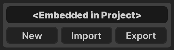
- : Clears the current model and creates a new empty model
- : Imports a model from an external
.lxmfile on disk - : Exports the current model to an
.lxmfile on disk
Syncing an Imported Model
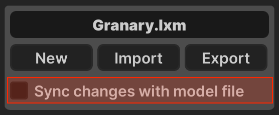
When an external model is imported, <Embedded in Project> is replaced by the name of the .lxm file that has been imported. If you make changes to the model, this is indicated by the addition of an asterisk after the model file name, e.g. Granary.lxm*.
An additional toggle box appears with the label Sync changes with model file. This box is unchecked by default, meaning that the imported model file is embedded directly into your project file. Future changes are not automatically written back to the external .lxm file.
When the sync box is checked, the external model file is also updated any time you save your project. Additionally, any time you open your project, the model is loaded directly from the external file rather than the internal copy, meaning that you will pick up any changes someone else may have made to the .lxm file on disk. Be careful using this option, as all projects using the model file must be able to adapt to any changes made.
Model files contain all Fixture and View settings, but do not contain the Output and Camera settings detailed below.
Output
The OUTPUT section defines fields that affect the network output. These settings have no effect on the rendering shown in the Preview Window.
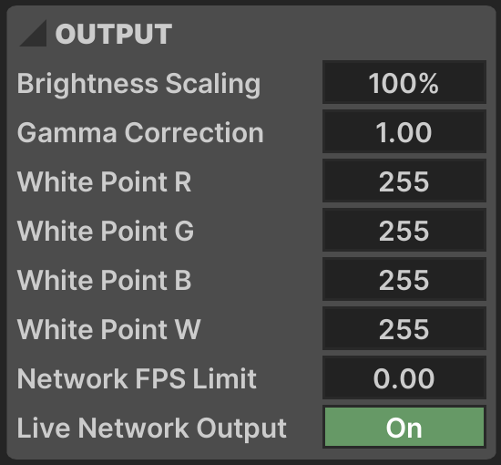
- Brightness Scaling: Scales brightness of network output
- Gamma Correction: Applies exponential gamma correction to network output (
1= no correction) - White Point R: Scales output R values to a maximum byte value
- White Point G: Scales output G values to a maximum byte value
- White Point B: Scales output B values to a maximum byte value
- White Point W: Scales output W values to a maximum byte value
- Network FPS Limit: Limits the maximum framerate of network output, independent of the engine setting in the Toolbar
- Live Network Output: Toggles whether network output is sent at all, also available on the Master channel in the Mixer
Camera
The CAMERA section specifies how the simulation is rendered in the Preview Window.
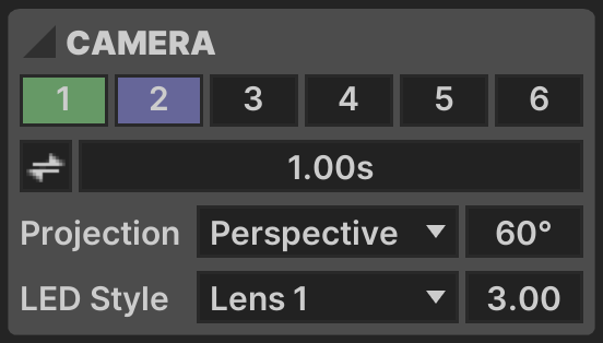
Six camera positions can be saved and recalled. At any given time, one camera is active and highlighted in the primary color. This camera's settings are automatically saved in real-time as it is adjusted. Camera slots with a saved position are highlighted in the secondary color. Transitions between camera positions can be enabled.
Camera positions can be recalled by pressing ⌥⇧1 - ⌥⇧6.
The following controls are not camera-specific.
- Animation: Whether to animate between camera positions
- Animation Time: Time to animate between positions
- Projection:
PerspectiveorOrthographicview - Perspective: Field-of-view angle for
Perspectiveprojection - LED Style: A choice of rendering style for each simulated LED
- Point Size: Size of individual point rendering
Further controls to customize the simulation are available in Preview Settings →